Building a VGA and Serial Keyboard Adapter for the SORD M68MX
The SORD M68MX has CHARACTER and GRAPHIC ports.
For the CHARACTER port, I've figured out the pinout for the minimum required functionality, so we can build a conversion adapter.
The wiring diagram is as follows:
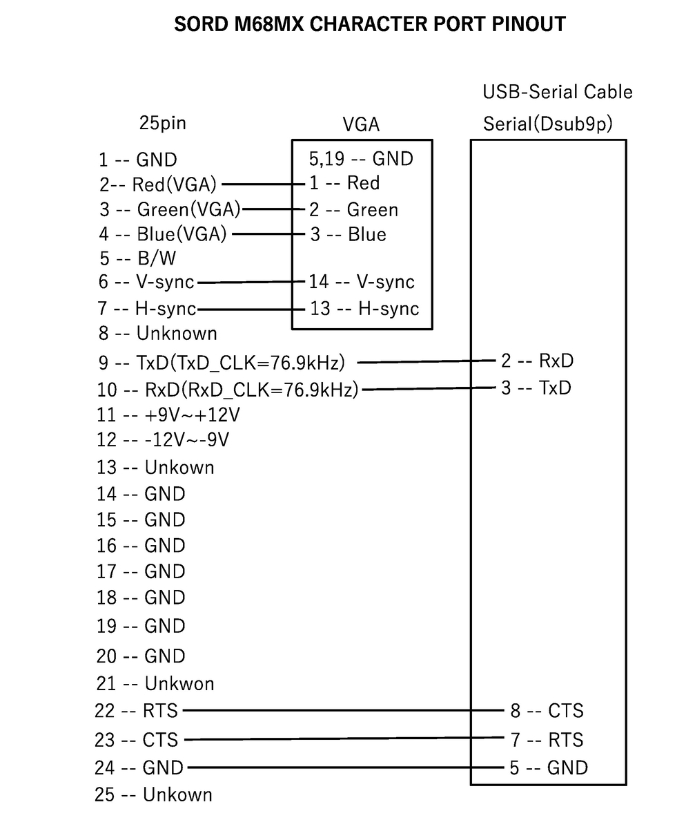
The 'Serial' in the wiring diagram shows the connections when using a USB-to-Serial cable. Serial keyboards weren't uncommon back in the M68MX era (like the EPSON QT-10, aka QX-10), but they're hard to find nowadays. On top of that, the M68MX's serial speed is 4800bps, which is slower than the commonly used 9600bps, so you'd need to adjust the settings on the serial keyboard side—but most are fixed-speed and can't be changed. So I think the modern solution is to use a USB-to-Serial cable. Of course, building one yourself is also an option.
The serial settings are 4800bps, 8N1. For the VGA monitor, I believe you'll need one that can display 24kHz.
With this setup, you can get display output and input working for everything except Graphics. You can also operate monitors like Sunbug.
SORD M68MXのVGA出力とシリアルキーボードを接続するアダプターを作成する
SORD M68MXはCHARACTERポートとGRAPHICポートを持っています。
CHARACTERポートについては、最低限の機能に必要なピンの配置がわかったので、変換アダプターを作ることができます。
結線図は以下の通りです。
結線図内のSerialはUSB-Serialケーブルを使用した場合の結線図です。
Serialを使用するキーボードは、M68MXの時代には珍しくなかった(EPSON QT-10(aka. QX-10)など)ですが、現代で見つけるのは困難です。更に、M68MXのシリアル速度は4800bpsなので、一般的に使用される9600bpsよりも遅く、シリアルキーボード側で設定を変える必要がありますが、大抵は速度固定で変更できません。よって、現代的な解決策はUSB-Serialケーブルを使用することだと思います。もちろん、作成するという手段もあります。
シリアルの設定は、4800bps、8N1です。VGAモニタは24kHzが映るものでないと駄目だったと思います。
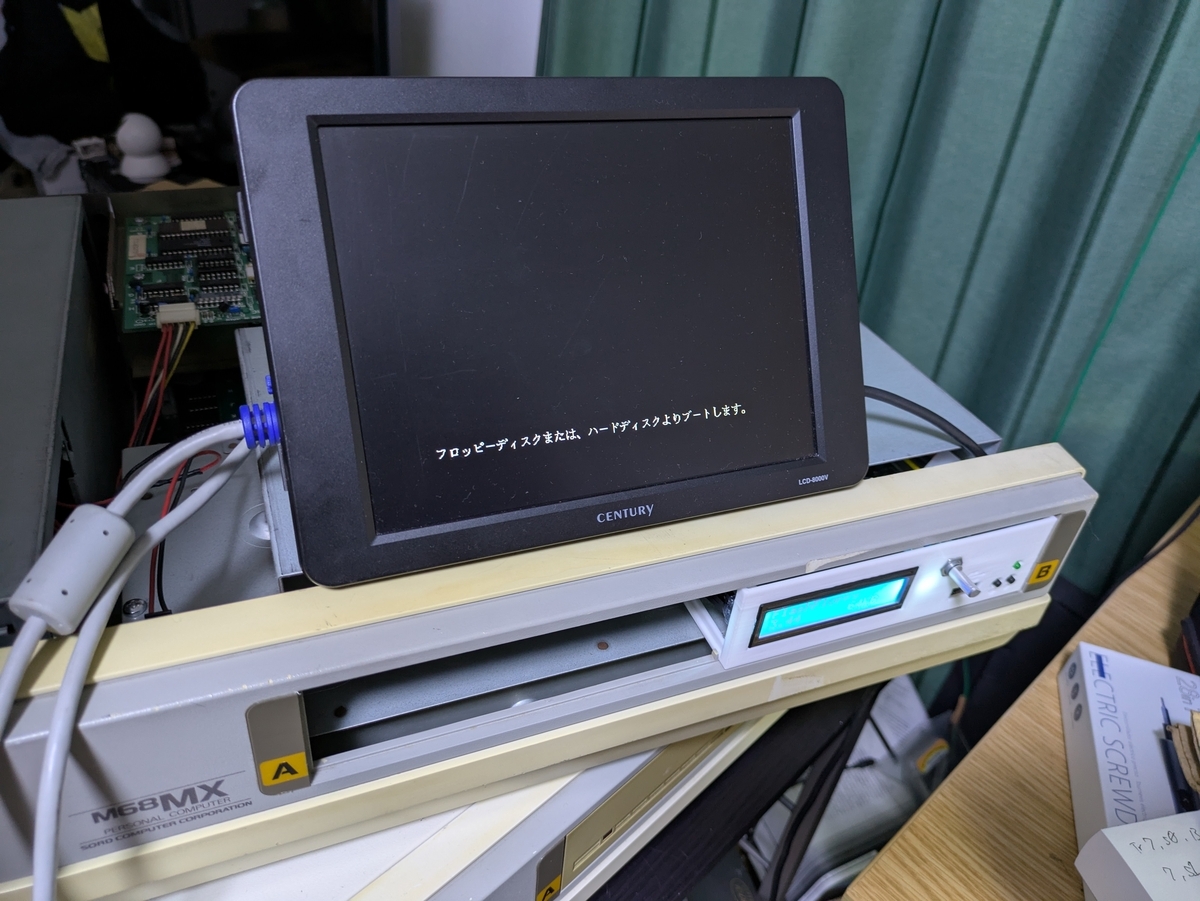
これでGraphic以外の表示と操作はできるようになります。Sunbugなどのモニタも操作できます。
How I Built a USB Keyboard Adapter for the SORD M68
I built a converter that allows a USB keyboard to be connected to the SORD M68.
Before diving into the details of the adapter, let’s first take a look at how the keyboard system of the SORD M68 works.
The keyboard interface circuit of the SORD M68 is structured as follows:
The keyboard connector pinout is as follows:
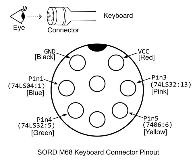
The important pins are Pin 1, Pin 3, Pin 4, and Pin 5.
The keyboard of the SORD M68 is connected to the machine’s “Z80 bus”, which also hosts various peripherals.
From the M68 side, timing signals for keyboard matrix scanning are provided, and the key-press information from the keyboard matrix is fed into a 74LS166, a parallel-to-serial shift register.
The resulting serial data is then sent onto the bus through the Qh pin of the 74LS166.
The concept behind this converter is to emulate the keyboard’s behavior by injecting USB keyboard key-press information into the 74LS166’s input lines (A to H) via a Raspberry Pi Pico 2.
When the /PE (/LOAD) signal of the 74LS166 falls, the parallel-to-serial conversion takes place, so the Pico 2 monitors this signal to synchronize with the M68’s scanning cycle.
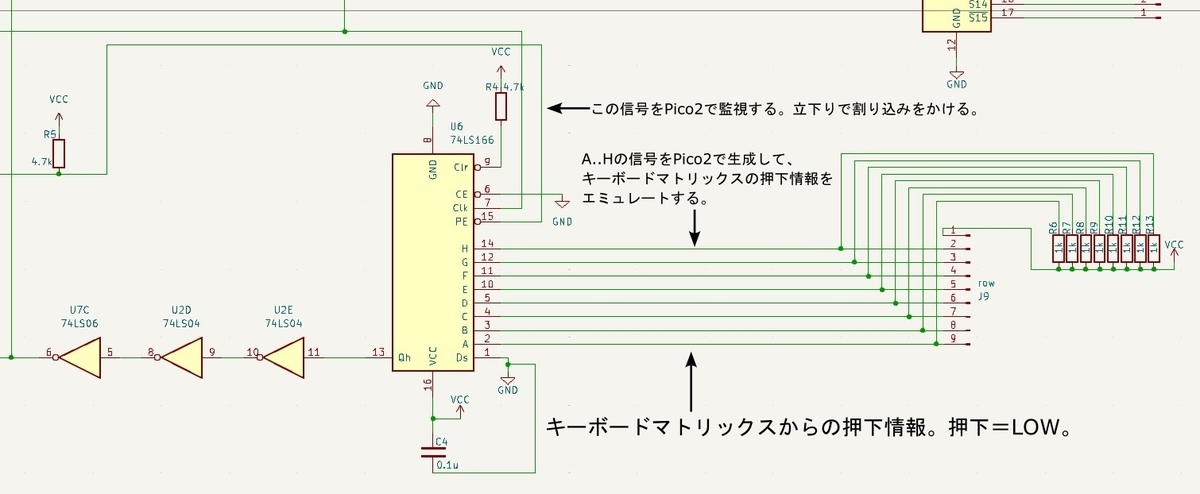
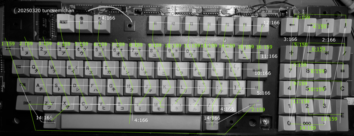
The image below shows how each IC is connected within the keyboard matrix.
For example, the label “11:166” indicates that this row is connected to pin 11 (F) of the 74LS166, while “1:159” indicates that the column is connected to pin 1 (/S0) of the 74159.
The scanning sequence proceeds in order from 1 to 15 on the 74159.
Pin 16 is not connected, so it is skipped during scanning.
The keyboard matrix signals are idle HIGH and go LOW when a key is pressed.
For instance, when the “A” key is pressed, it connects pin 2 of the 74159 and pin 5 of the 74LS166.
Therefore, during the second scan—that is, on the second falling edge of /PE—if the data 11101111 is output, the M68 recognizes it as an “A” keypress.
The scanned data is read into the M68’s I/O ports 0xE0 through 0xEF.
Among these, 0xEF is not scanned and therefore always reads zero.
Because of this design, if the Pico 2 loses track of which column is currently being scanned, it becomes impossible to obtain valid key-press information.
Therefore, the Pico 2 must start up as quickly as possible to ensure it does not miss the first falling edge of the /PE signal, and it must also never miss any subsequent ones.
In theory, the Pico 2’s processing speed should be sufficient for this task, but in practice it proved challenging to implement reliably.
As a workaround in the first version, I used two Pico 2 boards to distribute the workload — one dedicated to USB keyboard communication, and the other to generating key-press data for the M68.
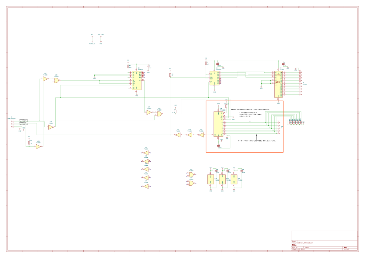
The schematic diagram is shown below.
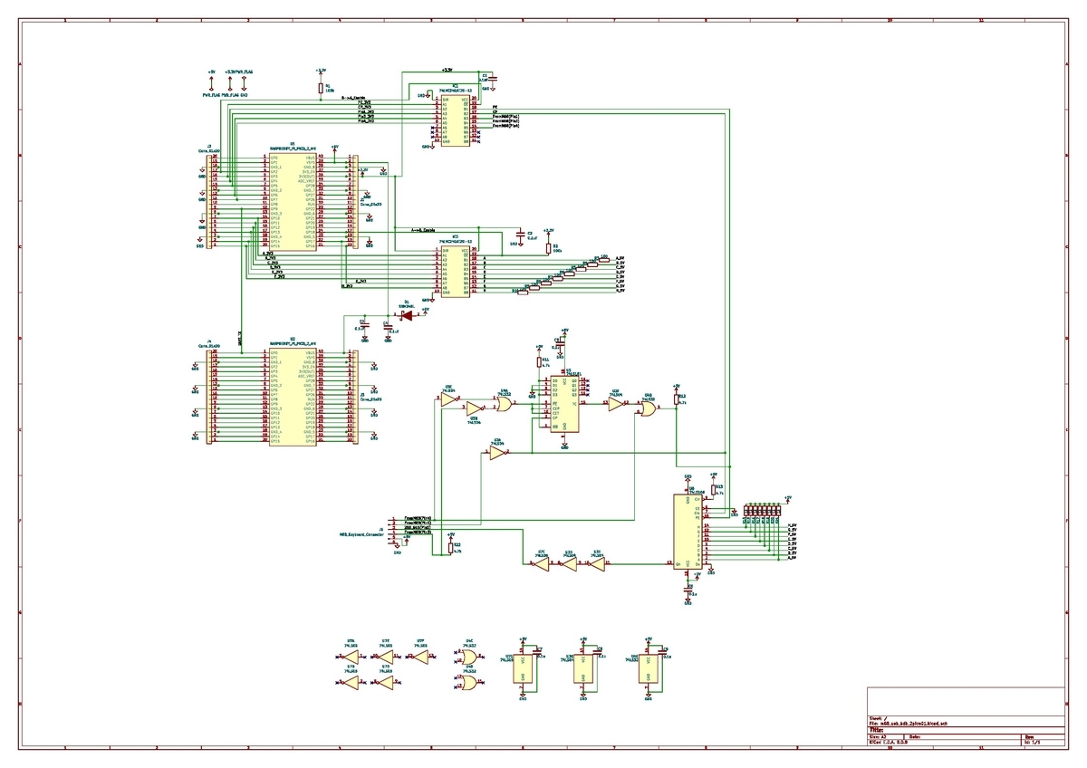
The schematic might look a bit small here, but you can check out the full KiCad files on my GitHub.
The firmware is also available in the same repository.
The code for the Pico 2 that receives USB keyboard key codes is also available on GitHub.
I also modified the CP/M-80 keyboard driver that I had previously ported for use with this converter.
The updated version has been uploaded to GitHub as well.
The file CPM62K_M68_20ms01.img is a raw disk image containing the revised CP/M-80 system.
SORD M68にUSBキーボードを接続するための変換器を作る
SORD M68にUSBキーボードを接続するための変換機を作りました。
一度、SORD M68のキーボード周りについてまとめます。
SORD M68のキーボードインターフェース回路は以下のようになっています。
キーボードコネクタのピン配置は以下のようになっています。
重要なのは、Pin1、Pin3、Pin4、Pin5です。
SORD M68のキーボードはSORD M68の"Z80バス"という各種ペリフェラルが接続されたバスに繋がれています。SORD M68側から、キーボードマトリックススキャンのタイミングが知らされ、キーボードマトリックスの押下情報がパラレル=シリアル変換器である74LS166のQhピンからシリアルデータとしてバスに流されます。
この変換器のコンセプトは、USBキーボードの押下情報をRaspberry pi Pico2を介して、74LS166の入力(A..H)に入れることでM68のキーボード押下情報に見せかけようというものです。74LS166の/PE(/LOAD)信号の立下りで、パラレルからシリアル変換が行われるので、この信号をPico2で監視します。
下の画像はキーボードマトリックスにおける各ICの接続状況です。例えば、"11:166"とあるのは74LS166の11番ピン(F)に接続されている行であることを示しています。同様に、”1:159"は、74159の1番ピン(/S0)に接続されている列であることを示しています。スキャンは、159の1..15の順に行われます。16番目は未接続なのでスキャンされません。キーボードマトリックスの押下情報はアイドルHIGHです。押下されるとLOWになります。
例えば、"A"キーを押した場合、"A"キーは74159の2番ピンと74LS166の5番ピンに接続されています。よって、2列目のスキャン、つまり、2度目の/PEの立下りで、11101111が出力されれば、M68によって"A"キー押下と認識されます。
スキャンしたデータはM68のI/Oポート0xE0~0xEFに入ります。スキャンされない0xEFは常に0です。
このような仕様の為、Pico2が現在スキャンしている列を見失うと、キー押下情報の取得は不可能になります。その為、Pico2は可能な限り素早く起動して、M68が最初の/PE信号立下りの瞬間を逃さないようにしなくてはなりませんし、以後も取りこぼしは許されません。Pico2の処理速度的には問題ないはずですが実現困難だった為、解決策として最初のバージョンでは負荷の分散を目的にPico2を2台用いて、USBキーボードとの通信用とM68キー押下情報生成用に分けて設計しました。以下が回路図です。
回路図が小さくて見づらいですが、kicadファイルをgithubにアップロードしています。
ソフトウェアも同じくgithubにアップロードしました。
USBキーボードのキーコードを受けとるPico2用のコードもgithubにあります。
この変換機用に以前移植したCP/M80のキーボードドライバを修正しました。これもgithubにアップロードしました。CPM62K_M68_20ms01.imgが、修正後のCP/M80が収録されたRawディスクイメージです。
2DDドライブに接続したgreaseweazle v4.1を使って、PC-6601のディスクイメージをフロッピーディスクに書き込む方法
greaseweazle v4.1を使って、PC-6601のディスクイメージを書き込みます。
gw.exe infoの結果は以下の通りです。
Host Tools: 1.22
Device:
Port: COM8
Model: Greaseweazle V4.1
MCU: AT32F403A, 216MHz, 224kB SRAM
Firmware: 1.6
Serial: GWB0BD79A75976C01007519705
USB: Full Speed (12 Mbit/s), 128kB Buffer
gw.exeには、PC-6601のプリセットは入っていないので、ディスク定義ファイルを作成します。
PC6601のディスクは一般的には、40トラック、1サイド、16セクタ、256バイト/セクタ、MFM記録です。全トラックが同様の設定とすると以下のようになります。
このファイルを、diskdefs_pc6601.cfgという名前で保存します。
以下のコマンドを実行します。この例では、sword3.imgを2DDフロッピーディスクに書き込みます。
.\gw.exe write --diskdefs=./diskdefs_pc6601.cfg --format=pc6601.1d --tracks=c=0-39:h=0:step=2 .\sword3.img --drive=0
--diskdefsにはcfgファイル名を入れます。--formatにはファイル内のフォーマット名を入れます。
この時、--tracksオプションをつけないとうまくいきません。2DDドライブで書き込んでいるので、step=2を入れないと正しく書き込まれません。
stepの意味は、2DDドライブにおけるヘッドを動かく移動量では記録密度が高くなりすぎて1Dドライブでは読めなくなるので、ヘッドの移動量を2倍にするという意味です。これで、1Dドライブで読める密度になります。これは1Dのフロッピーディスクでも、2DDのフロッピーディスクに書き込む場合でも同じです。
--drive=0はgreaseweazleとFDDの接続状況(使用ケーブル)によって変わります。今回は直結ケーブルなので0になっているようです。
ICレコーダー(SONY ICD-PX240)を使ってPASOPIA7のソフトを読み込ませる方法
データレコーダーの代わりにICレコーダー(SONY ICD-PX240)を使って、PASOPIA7のソフトを読み込ませる方法を記載します。
使用したのはPASOPIA7用S-OSです。このWAVファイルは既にGoogl Driveにアップロード済みです。このWAVファイルをUSB接続したICレコーダーに直接コピーしてもロードが終わりません。
WAVファイルの後ろに無音部分を追加するとうまくいきます。以下に方法が書いてあります。
無音部分を追加して、手順通りにロードすれば動作します。その際に、ICレコーダーの音量は24あたりが良いようです。
サンプリングレートが44100Hz、48000Hzのマイクでwhisper_micを使ってリアルタイム字幕する方法
固定サンプリングレートのUSBマイクを使ってWhisper_micを実行する方法
安価なUSBマイクをPC(ubuntu)につないで、Whisper_micを使用する方法を忘れないように記載します。
Whisper_micは、マイクのサンプリングレートを16000Hzに固定しています。一方で、最近のマイクは44100Hzか48000Hzの選択肢しかなく、単純に.asoundrcにrate文を書いても変更できません。また、Whisper_micのソースコード側を44100Hzx、48000Hzに修正しても動いているように見えて、音声認識がおかしかったです。
前段階として、soxやffmpegなどシステム側にコマンドをインストールしておきます。cudaを使う場合は、対応したデバイスドライバを入れておきます。
今回使用したGPUは、NVIDIA Geforce RTX2070 Super(8GB)です。
Pythonモジュール
必要なPyrhonモジュールをインストールします。Whisper_micをgitからcloneするとある
requirements.txtに書かれています。
numpy
tqdm
more-itertools
transformers>=4.19.0
ffmpeg-python==0.2.0
click
pyaudio
SpeechRecognition
pydub
git+https://github.com/openai/whisper.git
--extra-index-url https://download.pytorch.org/whl/cu113
torch
pynput
USBマイクの認識情報
今、arecord -lを入力して、以下の出力が得られました。USBマイクは、card 1として認識されていることがわかります。
**** List of CAPTURE Hardware Devices ****
card 1: Device [Usb Audio Device], device 0: USB Audio [USB Audio]
Subdevices: 1/1
Subdevice #0: subdevice #0
card 2: Generic [HD-Audio Generic], device 0: ALC892 Analog [ALC892 Analog]
Subdevices: 1/1
Subdevice #0: subdevice #0
card 2: Generic [HD-Audio Generic], device 2: ALC892 Alt Analog [ALC892 Alt Analog]
Subdevices: 1/1
Subdevice #0: subdevice #0
16000Hzにリサンプリングする
今回、.asoundrc内でplugin文を使ってリサンプリングすることで解決しました。.asoundrcを以下のように記載しました。一部重複しているのでこの部分は不要かもしれません。
pcm.!default {
type asym
playback.pcm {
type plug
slave.pcm "hw:1,0"
}
capture.pcm {
type plug
slave {
pcm "hw:1,0"
rate 16000
}
}
}
ctl.!default {
type hw
card 1
}
pcm.!default {
type plug
slave.pcm "plughw:1,0"
}
ctl.!default {
type hw
card 1
}
以下のpythonコードで、hw:1,0の記載が正しいか確認できます。
import pyaudio
for i in range(p.get_device_count()):
info = p.get_device_info_by_index(i)
print(f"Index {i}: {info['name']}")
p.terminate()
以下のコマンドで、ALSAに.asoundrcを読み込ませます。
sudo alsactl kill rescan
16000Hzで収録できるかチェックします。
arecord -f S16_LE -r 16000 test.wav
sox --i test.wav
以下のような出力が得られれば、16000Hzで収録できています。
Input File : 'test.wav'
Channels : 1
Sample Rate : 16000
Precision : 16-bit
Duration : 18:38:28.86 = 1073741824 samples ~ 5.03316e+06 CDDA sectors
File Size : 140k
Bit Rate : 16.7
Sample Encoding: 16-bit Signed Integer PCM
whisper_micは引数にmic_indexというマイクを識別する番号を渡す必要があります。下記のようなPythonコードを書いて確認します。
import pyaudio
for i in range(p.get_device_count()):
print(f"Device {i}: {p.get_device_info_by_index(i)['name']}")
p.terminate()
以下のような出力が得られました。他にも色々ALSAがなにか言ってきますが無視して問題ありません。
Device 0: HDA NVidia: HDMI 0 * (hw:0,3)
Device 1: HDA NVidia: HDMI 1 (hw:0,7)
Device 2: HDA NVidia: HDMI 2 (hw:0,8)
Device 3: HDA NVidia: HDMI 3 (hw:0,9)
Device 4: Usb Audio Device: USB Audio (hw:1,0)
Device 5: HD-Audio Generic: ALC892 Analog (hw:2,0)
Device 6: HD-Audio Generic: ALC892 Alt Analog (hw:2,2)
Device 7: hdmi
Device 8: pipewire
Device 9: default
USBマイクのmic_indexは4であることがわかります。しかし、ここで重要なのは、defaultが9であることです。.asoundrcではUSBマイクのリサンプリング後の出力をdefaultに流しています。ハードウェアの番号そのもの(この場合は4)を指定するとリサンプリングされていない44100Hzか48000HzのデータがWhisper_micに渡されるようです。
なので、以下のようにすることで、ようやくWhisper_micを利用できるようになります。以下の場合、modelサイズはsmall、cudaを利用して、ループ処理するという指定にしています。deviceにcpuを指定することもできるようですが遅いのではないかと思います。RTX2070 Super(8GB)では、モデルサイズはmediumまで動きました。
whisper_mic --model small --device cuda --mic_index 9 --loop
これで標準出力にマイクに話した日本語が出力されます。
